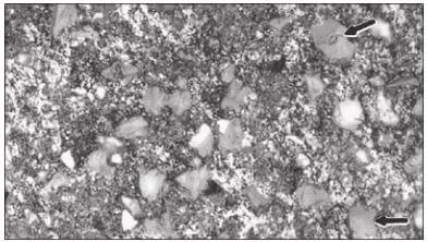
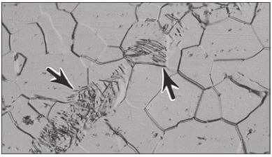
The grinding abrasives commonly used in materials preparation are silicon carbide (SiC), aluminum oxide (Al2O3), emery (Al2O3 – Fe3O4), composite ceramics and diamond. Emery paper is rarely used today in materials preparation due to its low cutting efficiency. SiC is more readily available as waterproof paper than aluminum oxide. These abrasives are bonded to paper, polymeric or cloth backing materials in the form of discs and belts of various sizes. Limited use is made of standard grinding wheels with abrasives embedded in a bonding material. The abrasives may be used also in powder form by charging the grinding surfaces with the abrasive in a premixed slurry or suspension. SiC particles, particularly with the finer size papers, embed easily when grinding soft metals, such as Pb, Sn, Cd and Bi (see Figure 3.1). Embedding of diamond abrasive is also a problem with these soft metals and with aluminum, but mainly with slurries when napless cloths are used, see Figure 3.2.
Silicon Carbide paper manufactured in the United States is typically made according to the ANSI/CAMI standard (B74. 18-1996) while paper manufactured in Europe are made according to the FEPA standard (43-GB-1984, R 1993). Both standards use the same methods for sizing the abrasives and the same standards to calibrate these devices (sieving for the coarsest grits, sedimentation grading for intermediate grits (240-600 [P280-P1200]), and the electrical resistance method for very fine grit sizes).
The grit size numbering systems differ above 180 grit [P180], but equivalent sizes can be determined using Table 3.1.

The chart shows the midpoints for the size ranges for ANSI/CAMI graded paper according to ANSI standard B74.18-1996 and for FEPA graded paper according to FEPA standard 43-GB-1984 (R1993). The ANSI/CAMI standard lists SiC particles sizes ranges up to 600 grit paper. For finer grit ANSI/CAMI papers, the particles sizes come from the CAMI booklet, Coated Abrasive (1996). *FEPA grades finer than P2500 are not standardized and are graded at the discretion of the manufacturer. In practice, the above standard values are only guidelines and individual manufacturers may work to a different size range and mean value.
As with many standards, they are not mandatory and manufacturers can, and do, make some of their papers to different mean particle sizes than defined in these specifications. There is a philosophical difference in the two systems. ANSI/ CAMI papers use a wider particle size distribution (centered on the mean size) than FEPA papers. A broader size range allows cutting to begin faster at lower pressures than with a narrower size range, so less heat is generated and less damage results. However, the broader size range does produce a wider range of scratch depths; but, these should be removed by the next step in the preparation sequence. Generation of less damage to the structure is considered to be more important than the surface finish after a particular grinding step, as it is the residual damage in the specimen that may prevent us from seeing the true microstructure at the end of the preparation sequence.

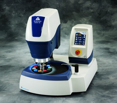
A Planar grinding machine, like the PlanarMet 300 planar grinding machine shown in Figure 3.3, utilizes a fixed abrasive stone for rapid sample grinding. This type of automated grinder produces planar samples in 1-2 minutes replacing up to 3 traditional grinding steps. Machines like this can be bench-top or floor standing and typically utilize the same sample holders as grinder-polishers to integrate the transition to the next step. Stationary grinding papers, often used by students, but uncommon in industrial use, are supplied in strips or rolls. The specimen is rubbed against the paper from top to bottom. Grinding in one direction is usually better for maintaining flatness than grinding in both directions. This procedure can be done dry for certain delicate materials, but water is usually added to keep the specimen surface cool and to carry away the grinding debris.
Belt grinders are usually present in most laboratories. These types of devices use coarse abrasive papers from 60 [P60] to 240 [P280] grit, and are mainly used for removing burrs from sectioning, for rounding edges that need not be preserved for examination, for flattening cut surfaces to be macroetched, or for removing sectioning damage.

Lapping is an abrasive technique in which the abrasive particles roll freely on the surface of a carrier disc. During the lapping process, the disc is charged with small amounts of a hard abrasive such as diamond or silicon carbide. Lapping discs can be made of many different materials; cast iron and plastic are used most commonly. Lapping produces a flatter specimen surface than grinding, but it does not remove metal in the same manner as grinding. Some platens, referred to as laps, are charged with diamond abrasive in a carrier, such as paste, oil based suspenstion or water based suspension. Initially the diamond particles roll over the lap surface (just as with other grinding surfaces), but they soon become embedded and cut the surface producing microchips.
Polishing is the final step, or steps, in producing a deformation-free surface that is flat, scratch free, and mirror-like in appearance. Such a surface is necessary to observe the true microstructure for subsequent interpretation, testing or analysis, both qualitative and quantitative.
The polishing technique used should not introduce extraneous structures such as disturbed metal (Figure 3.5), pitting (Figure 3.6), dragging out of inclusions, “comet tailing” (Figure 3.7), staining (Figure 3.8) or relief (height differences between different constituents, or between holes and constituents (Figures 3.9 and 3.10). Polishing usually is conducted in several stages.

Traditionally, coarse polishing generally was conducted with 6 or 3µm diamond abrasives charged onto napless or low-nap cloths. For hard materials, such as through hardened steels, ceramics and cemented carbides, an additional coarse polishing step may be required. The initial coarse polishing step may be followed by polishing with 1µm diamond on a napless, low nap, or medium nap cloth. A compatible lubricant should be used sparingly to prevent overheating or deformation of the surface.

Intermediate polishing should be performed thoroughly so that final polishing may be of minimal duration. Manual, or hand, polishing, is usually conducted using a rotating wheel where the operator rotates the specimen in a circular path counter to the wheel rotation direction.

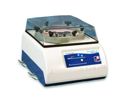
The term “mechanical polishing” is frequently used to describe the various polishing procedures involving the use of fine abrasives on cloth. The cloth may be attached to a rotating wheel or a vibratory polisher bowl. Historically, cloths have been either stretched over the wheel and held in place with an adjustable clamp on the platen periphery, or held in place with a pressure sensitive adhesive (PSA), magnetic or high friction surface- bonded to the back of the cloth. If a stretched cloth moves under the applied pressure during polishing, cutting will be less effective. If an automated polishing head is used, stretched cloths are more likely to rip, especially if unmounted specimens are being prepared. In mechanical polishing, the specimens are held by hand, held mechanically in a fixture, or merely confined within the polishing area, as with the VibroMet 2 polisher.


Mechanical polishing can be automated to a high degree using a wide variety of devices ranging from relatively simple systems, Figure 3.11, to rather sophisticated, programmable or even touch screen operated devices. Units also vary in capacity from a single specimen to a half dozen or more at a time and can be used for all grinding and polishing steps. These devices enable the operator to prepare a large number of specimens per day with a higher degree of quality than hand polishing and at reduced consumable costs. Automatic polishing devices produce the best surface flatness and edge retention. There are two approaches for handling specimens. Central force utilizes a specimen holder with each specimen held in place rigidly. The holder is pressed downward against the preparation surface with the force applied to the entire holder. Central force yields the best edge retention and specimen flatness. If the results after etching are inadequate, the specimens must be placed back in the holder and the entire preparation sequence must be repeated. Instead of doing this, most technicians will repeat the final step manually and then re-etch the specimen.
The second method utilizes a specimen holder where the specimens are held in place loosely. Force is applied to each specimen by a piston, hence the term “individual or single force” for this approach. This method provides convenience in examining individual specimens during the preparation cycle, without the problem of regaining planarity for all specimens in the holder on the next step. Also, if the etch results are deemed inadequate, the specimen can be replaced in the holder to repeat the last step, as planarity is achieved individually rather than collectively. The drawback to this method is that slight rocking of the specimen may occur, especially if the specimen height is too great, which degrades edge retention and flatness.
The requirements of a good polishing cloth include the ability to hold the abrasive media, long life, absence of any foreign material that may cause scratches, and absence of any processing chemical (such as dye or sizing) that may react with the specimen. Many cloths of different fabrics, weaves, or naps are available for specimen polishing. Napless or low nap cloths are recommended for coarse polishing with diamond abrasive compounds. Napless, low, medium, and occasionally high nap cloths are used for final polishing. This step should be brief to minimize relief. Table 3.2 lists current polishing cloths, their characteristics and applications.
 *Interchangeable in many of the following methods.

Polishing usually involves the use of one or more of the following abrasives: diamond, aluminum oxi (Al2O3), and amorphous silicon dioxide (SiO2) icollidal suspension. For certain materials, cerium oxide, chromium oxide, magnesium oxide or iron oxide may be used, although these the late 1920s, as Hoyt [7] mentions a visit to the Carboloy plant in West Lynn, Massachusetts, where he saw sapphire bearings being polished with diamond dust in an oil carrier. He used some of this material to prepare sintered carbides and published this work in 1930. Diamond abrasives were first introduced in a carrier paste but later aerosol and slurry forms were introduced. Virgin natural diamond was used initially, and is still available as MetaDi diamond paste. Later, synthetic diamond was introduced, first of the monocrystalline form, similar in morphology to natural diamond, and then in polycrystalline form. MetaDi II diamond pastes and MetaDi suspensions use synthetic monocrystalline diamond while MetaDi Supreme suspensions and MetaDi Ultra pastes use synthetic polycrystalline diamonds. Figure 3.13 shows the shape differences between monocrystalline and polycrystalline diamonds. Studies have shown that cutting rates are higher for many materials using polycrystalline diamond compared to monocrystalline diamond.

Colloidal silica was first used for polishing wafers of single crystal silicon where all of the damage on the wafer surface must be eliminated before a device can be grown on it. The silica is amorphous and the solution has a basic pH of about ~10. The silica particles are actually nearly spherical in shape, Figure 3.14, the polishing action is slow, and is due to both chemical and mechanical action. Damage-free surfaces can be produced more easily when using colloidal silica than with other abrasives during final polishing. Etchants can respond differently to surfaces polished with colloidal silica. For example, an etchant that produces a grain contrast etch when polished with alumina may instead reveal the grain and twin boundaries with a “flat” etch when polished with colloidal silica. Color etchants frequently respond better when colloidal silica is used producing a more pleasing range of colors and a crisper image. But, cleaning of the specimen is more difficult. For manual work, use a tuft of cotton soaked in a detergent solution. For automated systems, stop adding suspension about 10-15 seconds before the cycle ends and. For the last 10 seconds, flush the cloth surface with running water. Then, cleaning is simpler. Amorphous silica will crystallize if allowed to evaporate. Crystalline silica will scratch specimens, so this must be avoided. When opening a bottle, clean off any crystallized particles than may have formed around the opening. The safest approach is to filter the suspension before use. Additives are used to minimize crystallization, as in MasterMet 2 Colloidal Silica, greatly retarding crystallization.
For routine examinations, a fine diamond abrasive, such as 1µm, may be adequate as the last preparation step. Traditionally, aqueous fine alumina powders and suspensions, such as the MicroPolish II deagglomerated alumina powders and suspensions, have been used for final polishing with medium nap cloths. Alpha alumina (0.3µm size) and gamma alumina (0.05µm size) slurries (or suspensions) are popular for final polishing, either in sequence or singularly. MasterPrep alumina suspension utilizes alumina made by the sol-gel process, and it produces better surface finishes than alumina abrasives made by the traditional calcination process. Calcined alumina abrasives always exhibit some degree of agglomeration, regardless of the efforts to deagglomerate them, while sol-gel alumina is free of this problem. MasterMet colloidal silica suspensions (~10pH) are newer final polishing abrasives that produce a combination of mechanical and chemical action which is particularly beneficial for difficult to prepare materials. Vibratory polishers, Figure 3.15, are often used for final polishing, particularly with more difficult to prepare materials, for image analysis studies, or for publication of quality work.
Similarly to electro-polishing, vibratory polishing provides excellent surface finish without deformation and with minimal difficulty. The advantage of vibratory polishing over electro-polishing, however, is that it requires no hazardous chemicals and is suited to any material or mix of materials. The VibroMet 2 polisher generates a high frequency, variable amplitude vibrational motion, which is almost 100% horizontal without vertical movement. The sample is polished stress-free. After a few minutes to a few hours with no further intervention, samples are polished with excellent surface finish and sharply defined edges.

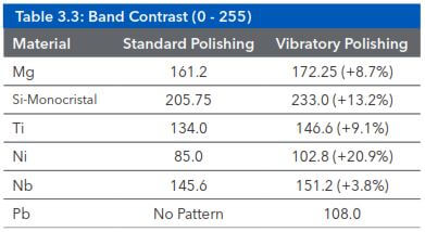
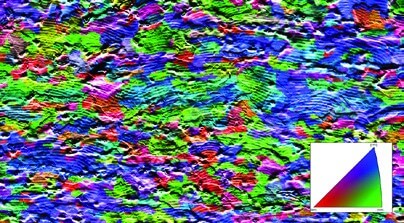
Polishing is typically carried out with fine diamond slurries or suspensions of oxides such as MasterMet, MasterPrep or MicroPolish. Vibratory polishing is particularly suitable for the preparation of sensitive or ductile materials. Samples polished using this technique are particularly suitable for high precision analysis techniques such as electron back-scatter detection (EBSD) or nano-indentation hardness testing. Such techniques are highly sensitive to small amounts of surface deformation, which often cannot be directly observed using standard preparation techniques. The Table 3.3 shows the improvement of diffraction band contrast due to a Vibratory polishing step. Figure 3.16 shows a vibratory polished ferritic steel.

Before vibratory polishing, the samples must be properly prepared using the methods described in this book including final polishing. High quality sample preparation is a basic starting point for this technique. As already explained above, vibratory polishing is dedicated to fine diamond or oxide suspensions typically between 1 and 0.02 microns.

As a recommendation, use the same polishing suspension as in the final stage of the standard mechanical preparation method. If the process uses a chemical additive such as hydrogen peroxide or other etchants, the addition will be optional on the VibroMet 2. Vibratory polishing is typically carried out without any additional chemical additives. The suspension should be sufficiently dispersed on the polishing cloth, and when using oxide suspensions particular care should be taken to ensure that the polishing cloth remains well moistened throughout the polishing cycle. If this is not done, then some polishing suspensions can crystallize. A popular compound for vibratory polishing is MasterMet 2 – a 0.02µm colloidal silica suspension that contains an additive to prevent crystallization.

The polishing cloth should be a flocked or napped cloth (such as MicroFloc, MicroCloth, MasterTex or VelTex), as the fibres in such cloths ease sample movement on the platen and help ensure a uniform polishing result.
Sample pressure is applied by the weight of the sample itself or by the addition of extra weights. The samples must be sufficiently rigid and typically should have a minimum total mass of 4 N [0.4 kg]. If the weight is too low, the samples could corrode or tarnish during the polishing.

There is no fixed rule for vibratory polishing time as this depends on many factors. One of the main factors is the amplitude strength, which is adjustable on the unit. This value changes the strength or intensity of the vibrations, which has a direct impact on the polishing time. In the case of new or unknown materials, the times can be determined empirically. Typically, if the polishing conditions are correct, a significant improvement can be seen in less than 30 minutes of vibratory polishing. The samples can then be examined under a light microscope or with a scanning electron microscope. If the polishing quality is not sufficiently improved, you can repeat the polishing cycle, or amend the polishing conditions.


Electrolytic Polishing and Etching Electrolytic polishing or etching is achieved by the completion of an electrical circuit through an electrolyte. The specimen is set as the anode in the circuit. The application of current drives an oxidizing chemical reaction at the anode to achieve dissolution of the metal at the surface of the specimen where it is in contact with the electrolyte.
The conditions under which such reactions occur can significantly affect the outcome of the reaction. These include:
- Current density (related to the area to be polished)
- Voltage
- Time
- Electrolyte composition, viscosity and temperature
- Electrolyte movement (“refreshing” the electrolyte in the area of the reaction)
Figure 3.21 is a schematic diagram showing the relationship between current density and voltage in such a polishing cell. At low voltages, rapid dissolution of the metal will result in etching, as different areas of the material are removed at different rates.
If the voltage is increased, passivation processes change the nature of the reaction and a polishing effect occurs. In this case, peaks on the surface dissolve preferentially, microscopically smoothing the surface. As this is purely a chemical effect, there is no associated mechanical damage from this process. As such, electrolytically polished surfaces are particularly useful for surface sensitive tests where even small amounts of surface deformation are unacceptable.
If the voltage is increased further, the passivation layer breaks down and oxygen is evolved, resulting in pitting at the surface of the specimen.

Electrolytic polishing and etching processes can be quick and effective, and highly reproducible when correctly performed. Historically, most applications for electrolytic polishing in metallography have been in process inspection of materials that are difficult to polish and etch with chemical etchants, such as superalloys and stainless steel – although soft materials are also ideal candidates, as mechanical polishing to a high standard can be difficult. The process has seen particular growth in metallography during recent years due to the increasing requirements for crystallographic analyses such as EBSD and surface characterization tests such as nano-indentation hardness testing, both of which require a deformation free surface to attain the best results.
Optimizing the reproducibility of electrolytic polishing and etching processes requires good control of the conditions. This is most readily achieved by using dedicated equipment, consisting of a good quality power supply unit and a polishing or etching cell that effectively controls the movement of the electrolyte as well as the area of the specimen. Figure 3.24 shows such a cell. It is recommended to use equipment that has integrated temperature control and cooling of the electrolyte, as heat can be generated during the process.

One of the common chemicals used in electrolytic polishing is perchloric acid, which can become unstable at higher temperatures (>100°F [38°C]) or higher concentrations or if higher concentrations occur due to excessive evaporation. Avoid the use of perchloric acid in contact with organic materials, such as mounting media, as unstable perchlorates can form and accumulate in the electrolyte.
Typical sequence for electropolishing of ferritic material:
- Step 1: Grinding with 400 grit [P800] and 600 grit [P1200] SiC-Paper on grinding machine (each 60s.)
- Step 2: Electrolytic polishing on electro polishing system ElectroMet 4 (Figure 3.25), at 30Vdc for 60 seconds
Sometimes, electro polished surfaces are wavy and this will cause a problem at higher magnifications. Electropolishing will tend to round edges or pores and wash out non-metallic inclusions. Two or more phase alloys are more difficult to polish, because the phases will preferentially attacked. Consequently, electrolytic polishing is not recommended for failure analysis, but can be used for a few seconds as a final polishing step to remove the last existing deformation.